RC Baja BUGATTI Type 57

Analysis
Summary
With the use of Free Body Diagrams and equilibrium equations learned in statics, students will determine the necessary loads and forces the car must withstand to meet the requirements specified by the individual student as well as the Baja Rules and regulations to survive and win the challenges of the Baja competition. The concepts learned in Mechanics of Materials would help determine the stresses the chassis and drivetrain must withstand during operation as well as determine the necessary sizes of bolt to secure the various components to one another. Analyses will be changing as the project car develops in order to accommodate the determined design parameters from future analyses.
Requirements for the car are as follows:
-
The race car must be made entirely by the team of students without any direct involvement from professional or automotive engineers, or any related professionals
-
Professionals may not make designs or decisions, nor fabricate parts for the team except as needed by shop rules and safety considerations
-
RC car must have only one propulsion motor per vehicle (other motors may be attached for other purposes but only one motor can be used for propulsion)
-
Only one battery can be used to for the propulsion motor (other batteries can be used for other functions but only one battery is allowed to power the propulsion motor)
-
Propulsion battery-pack is any 7.2-Volt 6-cell battery, or, any 7.4-Volt 2-cell battery or 2S LiPo RC battery when used with proper “balancing” charger and allied equipment, and must be securely mounted to the vehicle
-
Multiple servo motors are acceptable
-
Tires and traction devices must not leave marks on the venue’s floor
-
The body of the vehicle must not interfere with the inspection of the vehicle’s components
-
Necessary on-site damage-repairs to restore the vehicle are allowed if judges are notified of the simple necessity and general nature of the repairs
-
Transmitter frequencies must be unique and at least two channel numbers apart
-
The chassis should have a maximum deflection of 1/10” when dropped from a height of 1.5 feet
-
The vehicle should have a width of 8”-10”, length of 10”-1’ and a height of 6”-8”
-
Parts manufactured by 3D-printers or CNC machine can not exceed a length, width and height of 1.5’
-
The drivetrain and motor system should not exceed a temperature of 170 degrees F after 5 minutes of continuous use to avoid damaging the magnets in the motor
-
The vehicle must complete all three challenges without structural or engine failure
-
The vehicle should have a maximum weight of 12 lbs
-
The bodyshell should have quick release capabilities to allow for easy access to work on internal components
-
All points of connection between parts of the chassis and wheel bases should have at least 3 points of contact
-
During or immediately after operation the outer surface of motor less than 40 degrees C
-
Battery should last for at least 20 minutes of continuous operation
-
The vehicle must be able to withstand an impact force from a 25mph direct impact with an immovable object (a brick wall) without structural failure
-
The RPM of the axle must be obtained to determine the gear ratios necessary to transfer the RPM output of the motor to the axle
-
The vehicle can not have a maximum beam-deflection of more than 0.5mm
-
The drivetrain must function without failure at the intended input of 1700rpm to the differential for the rear axle of the car, all necessary calculations involving considered belts
-
The maximum torsional stress on the rear axle can’t exceed the yield strength of 1040 steel
-
The Driveshaft angle can not exceed 12 degrees from the horizontal for optimal performance
-
The chassis must withstand the pound force impact of hitting a wall at maximum the maximum speed of twenty-five miles per hour without buckling
-
The bending stress on the gears can not exceed the yield strength of steel (35 ksi)

In the analysis GSA-2 the primary focus was on making sure the vehicle can withstand an impact force of 25 miles per hours with an immovable object. With the use of Kinematics and conversion of energy, the predicted surface area of the Aluminum and the yield strength of the material; the resulting velocity necessary to make the material fail would be around 62.5 miles per hour which gives a factor of safety of 2.5. The result of this analysis showed the vehicle's width and height are able to withstand the maximum impact force.
Green Sheet Analysis (GSA) - 2

In analysis GSA-3, students focused on meeting the requirement of the vehicle to reach a top speed of 25 miles per hour. The analysis was to find the necessary RPM of the rear driving axle with the assumption that 100% of the motor is transferred to the axle and there is no slip. The analysis resulted in determining the driving axle must reach at least 1700PRM.
GSA - 3

GSA-4
Analysis GSA-4 focused on finding the necessary gear reduction ratio necessary to take the output RPM of the motor and reduce it to an acceptable input speed for the driving axle. The analysis utilized the gear and pulley ratios and center to center distancing to determine how far away the outside dimension of the motor would have to be form the outer diameter of the axle. The result of the analysis determined the two necessary gear ratios to transfer the output RPM of the motor to the required input RPM.
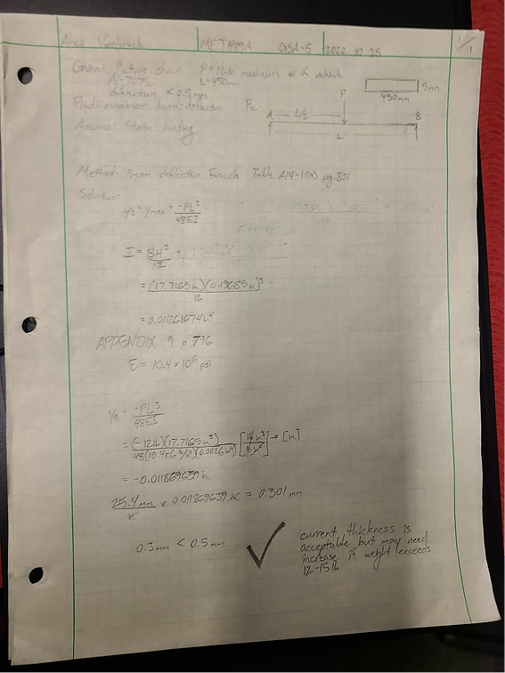
GSA-5
Analysis 5 focused on determining if the thickness of the chassis was thick enough to remain within the acceptable deflection tolerance of less than 0.5mm; this analysis was in relation to requirement #23 (the beam-deflection of the car can not be more than 0.5mm). The analysis focused on the use of beam-deflection formulas based on table A14-1 on page 801 and the resulting calculations determined with the maximum overall weight of 12lbs would only cause a deflection of about 0.3mm which is within the predetermined tolerance. All associate calculations are located in Appendix A05 in figure GSA-5.
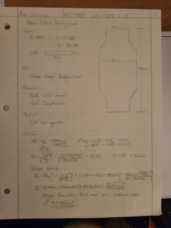
GSA-11
This analysis focused on finding the critical buckling load of the chassis by making use the critical bucking load equation involving Johnson’s formula in the related chapter of Mott’s, SR<CC and Johnsons critical load formula, Pcr = A*Sy[1-{(Sy*Sr^2)/((4π^2)*E))}]. The associated requirement was #27, the chassis must withstand the impact of a full speed contact without buckling and from the analysis the chassis can withstand an impact of 254 kN equivalent to 57,100 lbf which is more than the calculated impact force experienced from a 25 mph hit is 51,024 lbf; this proves the cross sectional area is large enough to withstand the impact as mentioned in GSA-11 in Appendix A11. With a design facter of 2, the allowable load is 28,550 lbf